Share
Pin
Tweet
Send
Share
Send
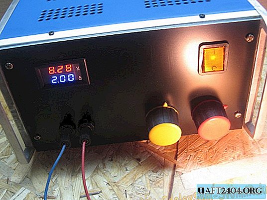
I have an adjustable power supply. Only voltage is regulated; accordingly, there is no current adjustment. For some purposes it is enough. I decided to assemble a unit with adjustable current and voltage. Laboratory power supply, then LBP, is a very necessary thing.
The LBP circuit is very simple, since I will use the DC-DC converter module from China.
Characteristics
The main characteristics of the module:
- Input voltage 5 - 40 Volts;
- Output voltage 1.2 - 35 Volts;
- Output current (max) 9 Amps, it is advisable to install a cooler.
Power supply circuit
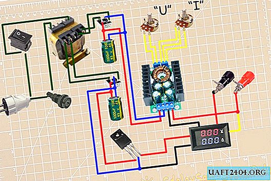
As already mentioned, the scheme is simple. Mains voltage is supplied to the transformer. There is a mains switch and a fuse. The voltage is reduced by the transformer. The top honor of the power circuit. Alternating voltage is supplied to the diode bridge and a smoothing capacitor. It then goes to the DC-DC converter. Voltage is supplied from the converter to the output terminals. The minus of the circuit is broken by the instrument. For convenience, the control resistors are removed from the board.
The bottom is designed to power the multimeter. The transformer has a separate winding. As with the power winding, alternating voltage is supplied to the diode bridge and filter capacitor. Next, I installed a linear stabilizer at 5 Volts.
Components
We figured out the scheme. Now go to the components.
The case of the LBP will be the old case from the regulator of the soldering iron. Soldering iron regulator from the time of the USSR. Very solid.

The front panel will be made of composite plastic. The plastic consists of two aluminum plates and a plastic between it. On the one hand, it is white, on the second black. The black side will be front.

A step-down transformer from old equipment, I don’t remember which one. It had to be slightly modified. He made a tap on 22 Volts, a full winding on 27 Volts. If you leave, then after the diode bridge voltage is more than 30 volts. This is a lot for the 7805 stabilizer installed on leech = // DC-DC converter / leech. It powers the operational amplifier circuit. Although it is declared 40 Volts, taking into account the maximum for 7805 at 30 Volts.

DC buck converter.

Voltammeter for 3 segments. For a more accurate display of the output parameters, you need to apply to the 4th segment. What I had, I applied it.

Terminals of the USSR. Strong and reliable.

4700 uF Capacitor * 63 Volts. Based on 1000 microfarads per 1 ampere. An additional 2 * 470 microfarads are installed on the module.

The diode bridge can also be taken as a single one, but I still have the old project. Assembled on 4 diodes D242.

Manufacture
We mark the bottom of the case, drill holes for: transformer, diode bridge, module. All solder accordingly circuit. I pulled out two tuning resistors from the module. Instead, soldered wires. On current 3 wires, on voltage two.

I will power the multimeter through a linear stabilizer of 5 volts. KTs402 diode bridge and small capacitor.

On the rear panel I make markings for the network connector and fuse. I carefully cut and install everything.

On the front panel, I mark and cut out all the holes. There will be: output terminals, network switch, current and voltage resistors, voltammeter.

Soldered all the elements installed inside. A power switch connects both network wires. Originally wanted to apply another.

Install all the elements of the front panel. The plus terminal is marked in red. Handles of resistors of different colors. Red in color display volt. Yellow current. So far I have not signed where the current and voltage are. Later I will change the resistors to multi-turn, I can also change the handles.

I painted the top cover. There was too much gap between the front panel and the cover; it was covered with a small corner. When checking, the unit gave out 9 Amperes at short, at 28 Volts, which amounted to slightly more than 250 Watts.

Such is the Laboratory Power Supply turned out. They can both power various devices, and also charge batteries. Initially, I wanted to use a 24 Volt pulse source, but I got a transformer of the required dimensions. Also, I try to assemble the device from what is. Thank you all for your attention!
Share
Pin
Tweet
Send
Share
Send


